Introduction
Feedback control, instead of preprogramed posture strategies, has been accepted to control posture in human standing balance task. Studies have been done trying to understand the feedback control system and controllers have been got from the standing balance experimental data. However, most of them could not be applied on engineering devices, for instance, humanoid robots and P/O devices, due to the nonparameteric control sturtures and perturbation amplitude related control gains.
In this study, we proposed that there exists general feedback controllers among healthy human to keep standing balance. Here, general means controller parameters do not change according to perturbation characters. We conducted standing balance experiment under the random distance perturbation of the standing platform. Then we identify parameteric state feedabck controllers (not perturbation amplitude related) in the time domain. The identified controllers have the potential to be used in humanoid robots and P/O devices.
Method
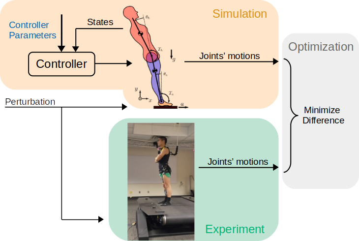
In this project, we first did human standing balance experiment to collect data. Then we developed a stochastic identificaiton method to gurantee that the identified state feedback controllers are stable. Finally, we identified both linear and nonlinear feedback controllers from the collected experimental data.
Human Standing Balance Experiment
Eight able bodied subjects including one female and seven males with an average age of \(27 \pm 5.3\) years, height of \(1.71\pm0.08\) m, mass of \(65.3\pm9.2\) kg participated in the study. This study was approved by the Institutional Review Board of Cleveland State University(# IRB-FY2018-40).
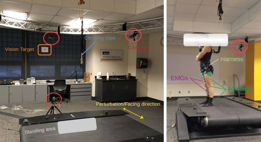
In the experiment, twenty-seven markers were used to track the participants' movements. Five extra markers were placed on the standing platform to record its movement during experiment. Nine Electromyography (EMG) sensors were used in the experiment to record nine muscle activations in the right leg. A four degree of freedom (DOF) V-Gait (Motek Medical) was used as standing plate and to apply perturbation. Six DOF force sensors were built in the V-Gait and used to detect ground reaction forces during experiment. Experiment setting is shown here.
In the experiment, perturbation was designed as random square wave signal. Parameters that determined random square wave signal are amplitudes and stage duration. Participants were instructed to keep their vision on the horizontal target, having the feet width similar to the width of shoulder, and feel free to bend the trunk to keep balance.
More detail of the experiment and results can be found in the chapter III of my dessertation.
Stochastic Optimization
Background: System identification can be used to obtain a model of the human postural control system from experimental data in which subjects are mechanically perturbed while standing. However, unstable controllers were sometimes found, which obviously do not explain human balance and cannot be applied in control of humanoid robots. Eigenvalue constraints can be used to avoid unstable controllers. However, this method is hard to apply to highly nonlinear systems and large identification datasets.
New method: To address these issues, we perform the system identification with a stochastic system model where process noise is modeled. The parameter identification is performed by simultaneous trajectory optimizations on multiple episodes that have different instances of the process noise.
Results: The stochastic and deterministic identification methods were tested on three types of controllers, including both linear and nonlinear controller architectures. Stochastic identification tracked the experimental data nearly as well as the deterministic identification, while avoiding the unstable controllers that were found with a deterministic system model.
Comparison with Existing Method: Comparing to eigenvalue constraints, stochastic identification has wider application potentials. Since linearization is not needed in the stochastic identification, it is applicable to highly nonlinear systems, and it can be applied on large data-sets.
Conclusions: Stochastic identification can be used to avoid unstable controllers in human postural control identification.
For more detail, please check my peer-reviewed paper .
Standing Balance Controller Identification
An indirect identification approach was used in this study to avoid the bias of direct identification. In the indirect approach, a closed-loop system including human body dynamics, feedback controller were built to represent the human standing balance system.
Five types of feedback controllers were used in this paper to identify control parameters on the collected experimental data. Two of them are linear: proportional-derivative (PD) controller and full-states proportional-derivative (FPD) controller. The other three are nonlinear: linear states combination with time delay (LSCTD) controller, neural network (NN) controller, and neural network with time delay (NNTD) controller. The formulas of these five controllers are shown below.
Proportional-Derivative (PD) Controller:
$$ begin{bmatrix} T_a(t)\ T_h(t) end{bmatrix} = begin{bmatrix} K_{p_a} & 0 & K_{d_a} & 0\ 0 & K_{p_h} & 0 & K_{d_h}\ end{bmatrix} begin{bmatrix} theta_a(t) - theta_a^{ref} \ theta_h(t) - theta_h^{ref} \ dot{theta}_a(t) \ dot{theta}_h(t) end{bmatrix} $$
Full-States Proportional-Derivative (FPD) Controller:
\begin{equation*} \begin{equation}\label{FPD controller type} \begin{bmatrix} T_a(t)\\ T_h(t) \end{bmatrix} = \begin{bmatrix} K_{p_{aa}} & K_{p_{ah}} & K_{d_{aa}} & K_{d_{ah}}\\ K_{p_{ha}} & K_{p_{hh}} & K_{d_{ha}} & K_{d_{hh}}\\ \end{bmatrix} \begin{bmatrix} \theta_a(t) - \theta_a^{ref} \\ \theta_h(t) - \theta_h^{ref} \\ \dot{\theta}_a(t) \\ \dot{\theta}_h(t) \end{bmatrix} \end{equation} \end{equation*}
Linear States Combination with Time Delay (LSCTD) Controller:
\begin{equation*} \begin{equation}\label{LSCTD controller type} \begin{bmatrix} T_a(t)\\ T_h(t) \end{bmatrix} = \sum_{m=0}^{D} \left( \begin{bmatrix} K_{p_{aa}}^m & K_{p_{ah}}^m & K_{d_{aa}}^m & K_{d_{ah}}^m\\ K_{p_{ha}}^m & K_{p_{hh}}^m & K_{d_{ha}}^m & K_{d_{hh}}^m\\ \end{bmatrix} \begin{bmatrix} \theta_a(t-m*\delta t) - \theta_a^{ref} \\ \theta_h(t-m*\delta t) - \theta_h^{ref} \\ \dot{\theta}_a(t-m*\delta t) \\ \dot{\theta}_h(t-m*\delta t) \end{bmatrix} \right) \end{equation} \end{equation*}
where $T_a(t)$ is ankle joint torque at time point $t$ and $T_h(t)$ is hip joint torque at time point $t$; $theta_a(t)$ and $theta_h(t)$ are ankle and hip joint angles at time point $t$; $dot{theta}_a(t)$ and $dot{theta}_h(t)$ are ankle and hip joint angular velocities at time point $t$; $theta_a(t-m*delta t)$ and $theta_h(t-m*delta t)$ are ankle and hip joint angles at $m^{th}$ point prior to the current time point $t$; $dot{theta}_a(t-m*delta t)$ and $dot{theta}_h(t-m*delta t)$ are ankle and hip joints angular velocities at $m^{th}$ point prior to the current time point $t$; $K_p$ and $K_d$ are proportional and derivative gains of feedback controllers multiplied with the state at time point $t$. $K_p^m$ and $K_d^m$ are proportional and derivative gains of feedback controllers multiplied with the state at $m^{th}$ point prior to the current time point $t$.\
Neural Network (NN) Controller:
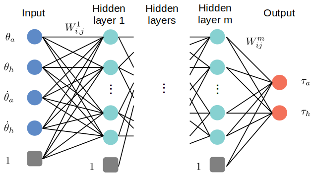
NN controller was defined as standard neural network with one hidden layer and four hidden nodes. It is nonlinear controller, since its activation function is a nonlinear function. The inputs of the NN controller are four states and outputs are two torques. Besides, one constant node (unit input) was added at both input and hidden layer. The activation function used in NN controller is smoothed leaky-ReLU function. The reason of smooth is to make it differentiable at all points. The general structure of neural network is shown here.
The smoothed activation function is:
\begin{equation*} \begin{equation}\label{Activation Function} f(x) = x + 0.7(\frac{x-\sqrt{x^2+0.0001}}{2}) \end{equation} \end{equation*}
Neural Network with Time Delay (NNTD) Controller:
NNTD controller used the same neural networking settings but with one hidden layer and eight hidden nodes. The difference is that the inputs of the NN controller are four current states and prior states (delay inputs). Outputs of NNTD controller are two torques.
More details of this work, please check chapter V of my dessertation.


